The Gigabyte B343-C40-AAJ1 is really neat. It houses ten AMD EPYC 4005 (or Ryzen 9000) nodes in a 3U chassis. What is more, each node has a lot of functionality, mirroring a full node, just in a much more compact form factor. What is more, Gigabyte is doing something neat with the networking that further lowers the cost of deploying these nodes. Let us get to it.
Gigabyte B343-C40-AAJ1 External Chassis Overview
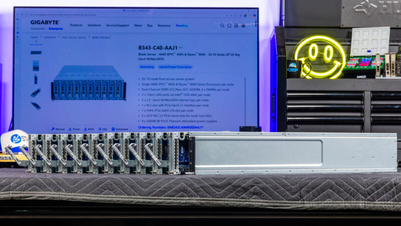
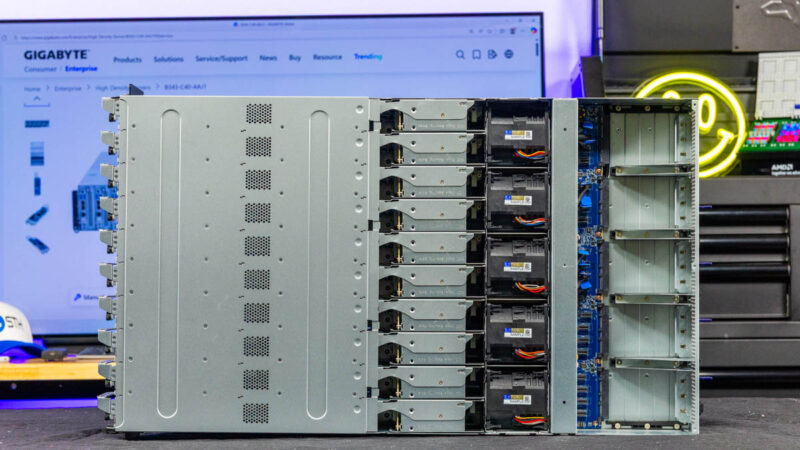
The chassis is a 3U tall and only 770mm or just over 30in deep. When you compare that to ten 1U servers, this is much more compact while still fitting in many lower-cost shorter-depth racks.
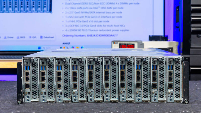
The front is solely focused on the ten nodes. We will focus on those after we get through the chassis.
On the back of the chassis, we get a lot of venting for airflow, but then four power supplies,
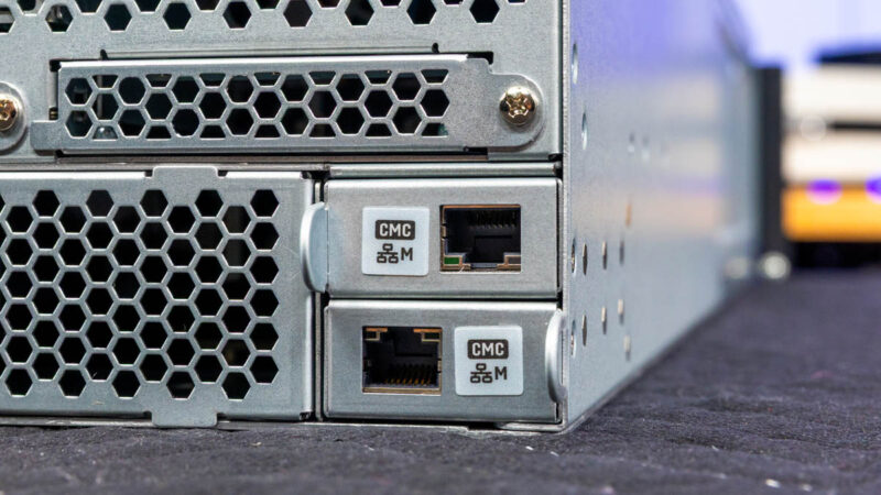
two management ports, and OCP NIC 3.0 slots.
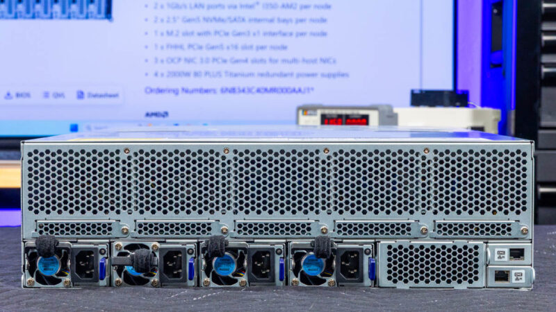
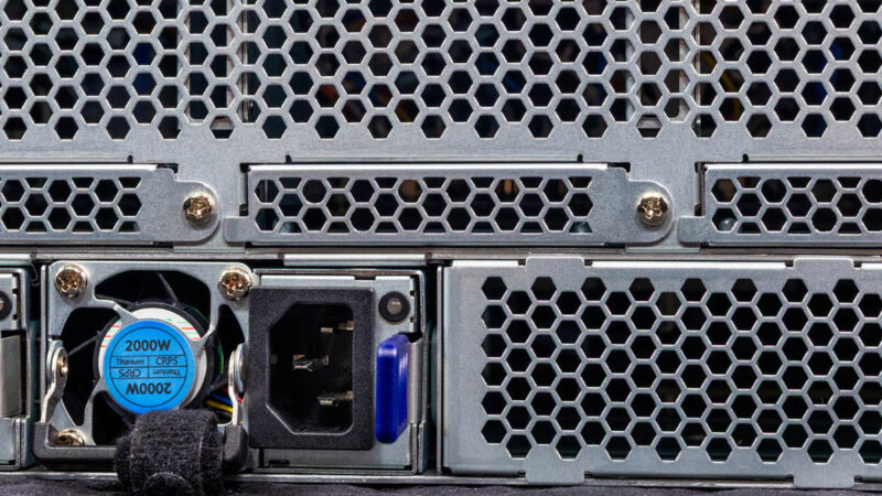
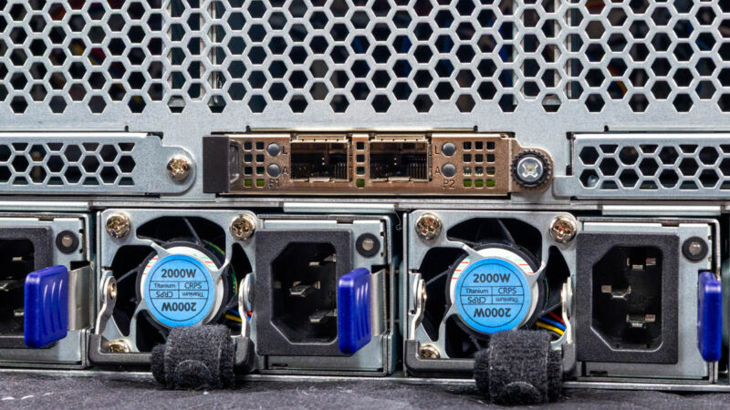
The power supplies are 2kW Titanium rated power supplies. If you were to have single node per 1U servers instead, these save a lot of components.
Ten servers with redundant power supplies would mean twenty power supplies. That also means twenty PDU ports. Instead, we have four power supplies for ten nodes, or one fifth as many.
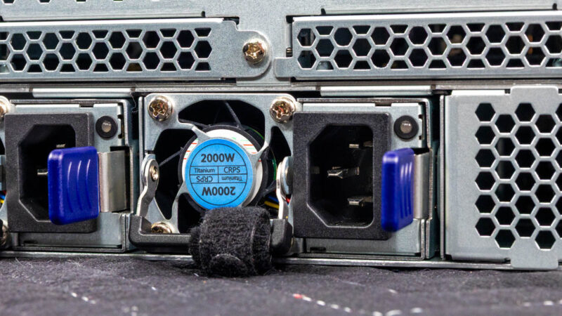
Here is a quick look at the Gospower power supplies.Gigabyte B343 C40 AAJ1 2000W 80 PLUS Titanium Redundant Power Supplies 2Here are two CMC ports. As we have seen on Gigabyte 2U 4-node servers previously,
Gigabyte has a feature to have a shared management interface on multi-node systems.This may not seem like a big deal at first, but instead of ten management ports, this allows Gigabyte to require fewer management switch ports.
Then there are the OCP NIC 3.0 slots.
Three of these take OCP NIC 3.0 multi-host adapters. This is a really neat feature since it allows you to add three higher-speed NICs and service all ten nodes.
Just like the power and management savings on ports and cabling, using three higher speed NICs instead of putting 10GbE NICs in each node.
Next, let us get inside the system to see how the ten nodes are connected.
Gigabyte B343-C40-AAJ1 External Chassis
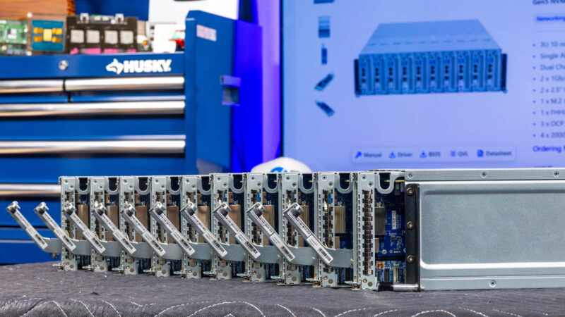
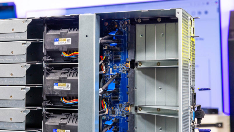
Here is what the system looks like from the rear of the nodes, through the fans, to the OCP NIC 3.0 slots, and then to the rear of the chassis.
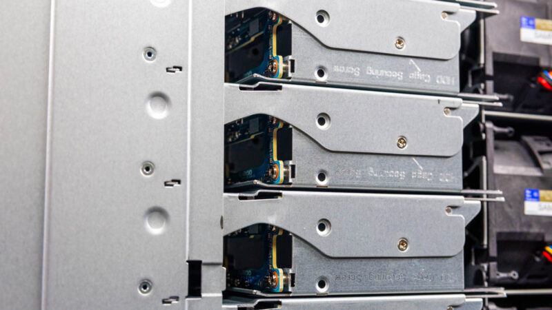
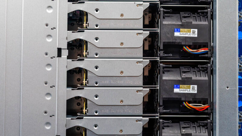
Here is the rear of the nodes where the 2.5″ SATA drives are located.
Behind those, we have the fan modules.
This shared chassis design also massively reduces the need for fans.
Behind the fans we have the connectors for the OCP NIC 3.0 slots.
These cabled connections provide x4 lanes to the PCIe Gen4 slots.
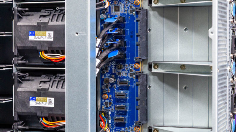
Here you can see the other slots. Something to keep in mind is that only three of the five slots are connected in this chassis.

